


 En
En

Using a Raspberry Pi and the OpenPLC software platform, create a simple PLC that can be programmed in ladder diagrams with remote access and I/O monitoring dashboards.
OpenPLC provides a control engineering development platform that transforms various microcontrollers into programmable logic controllers. OpenPLC is compatible with platforms including the Arduino Uno, ESP32, and RP2040, and even single-board computers like the Raspberry Pi can be used as a PLC with the editor, a runtime engine, and a web server.
This project article will explain the steps used to create a PLC with a Raspberry Pi using OpenPLC.
Although a simple, unprotected board computer might not stand up to a harsh industrial environment, nor inherently contain I/O terminals with industrial voltage ratings, this software solution removes the first barrier of implementing the command logic and interfacing with the I/O points, a critical step in the journey of automation.
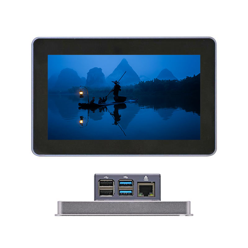
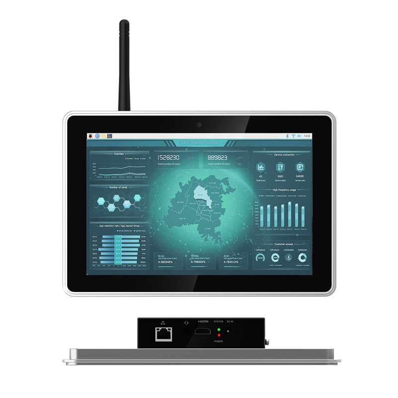
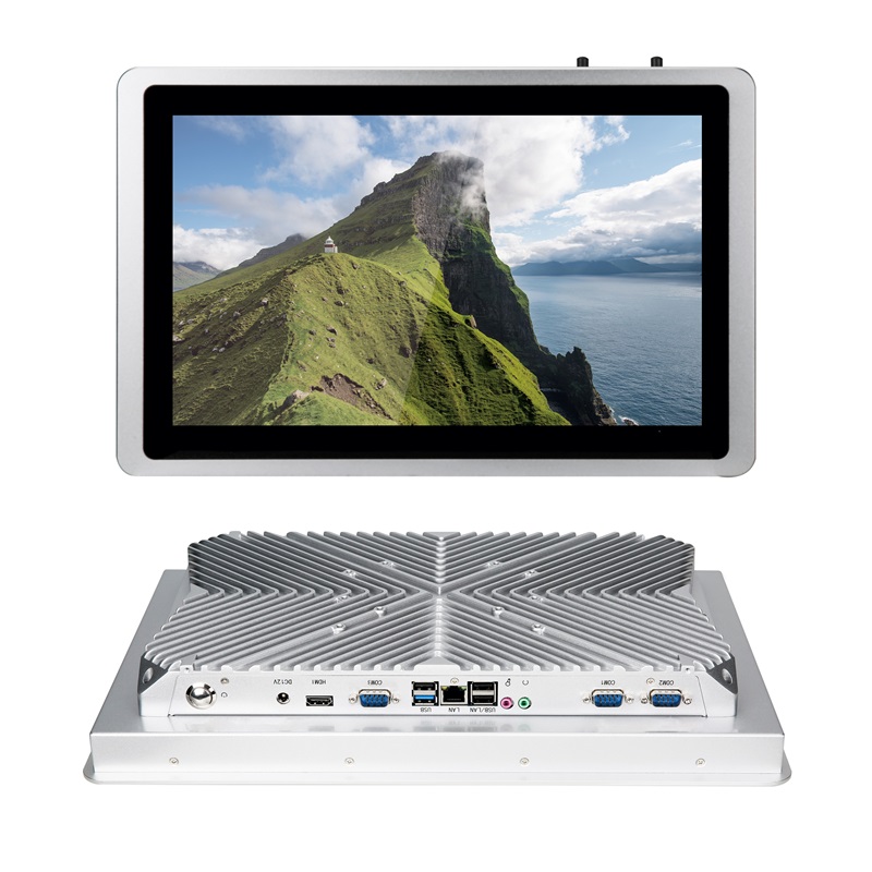
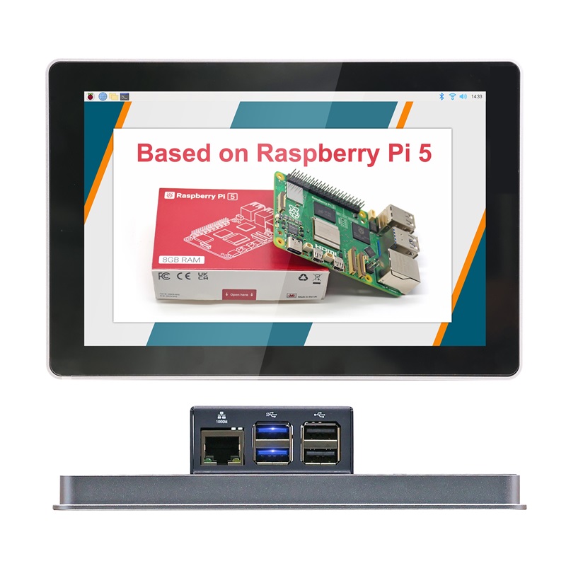
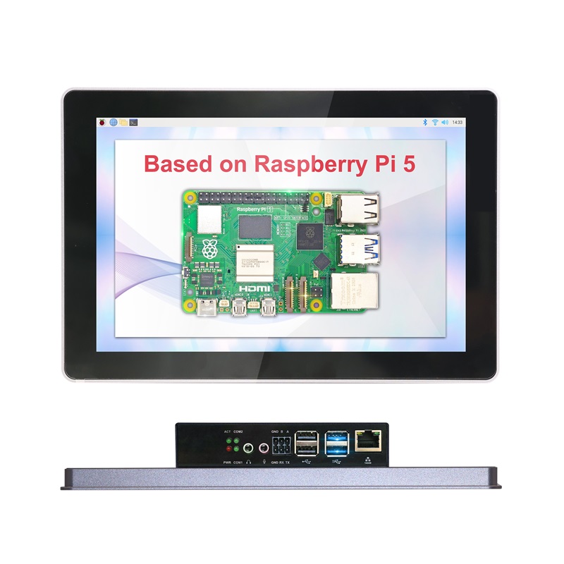
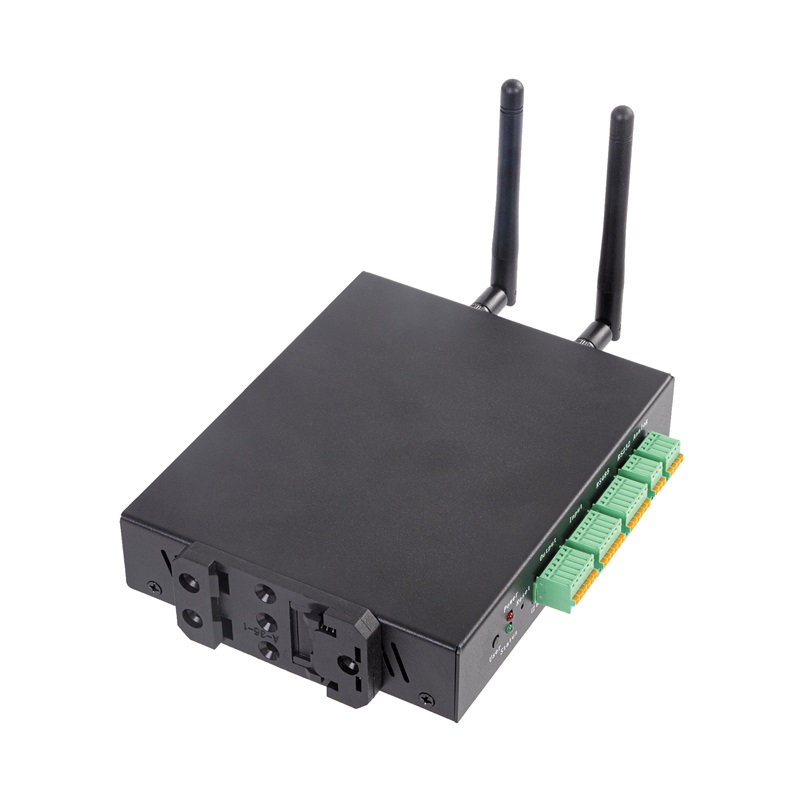
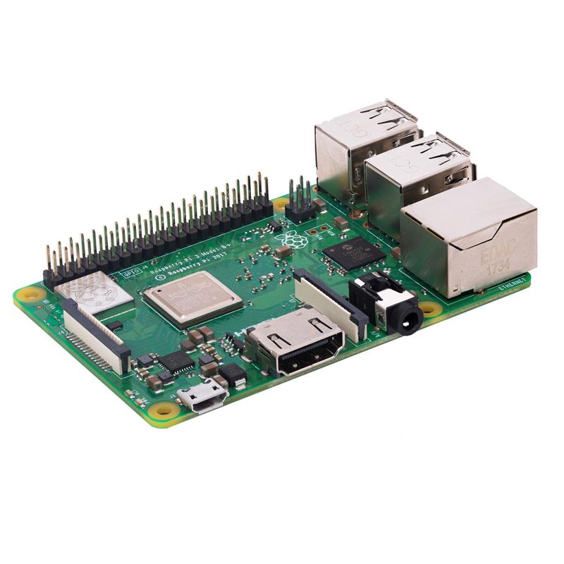
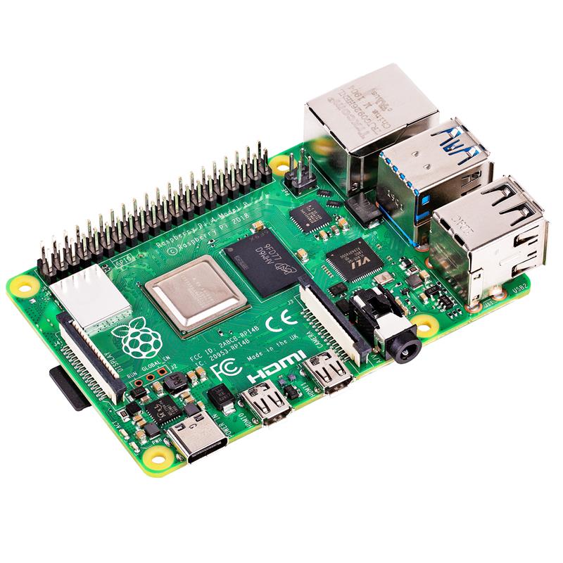
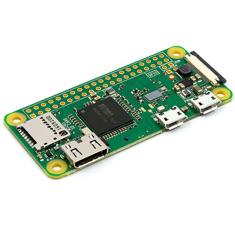
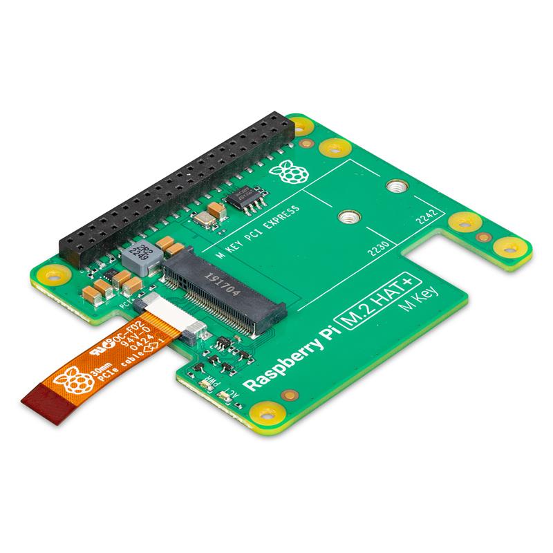
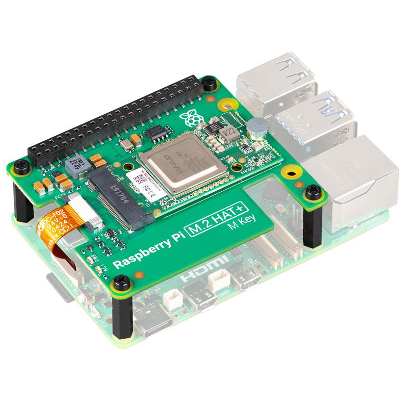
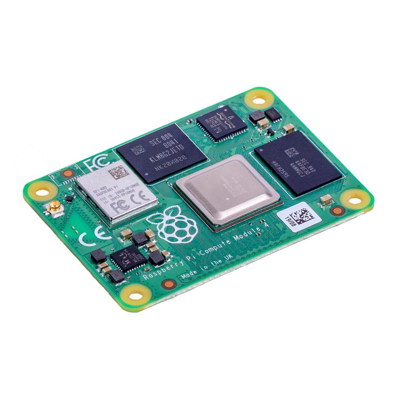
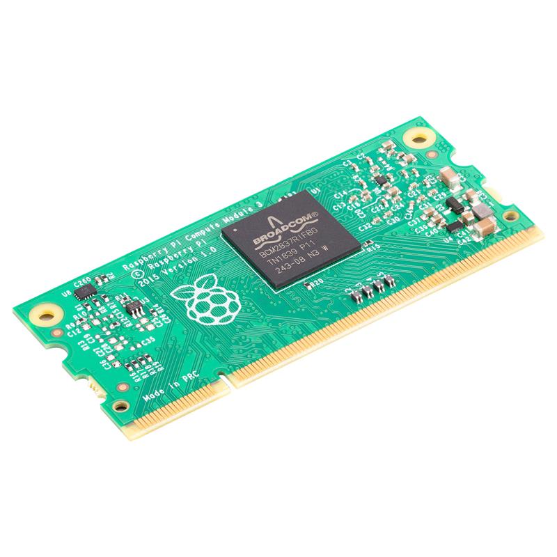
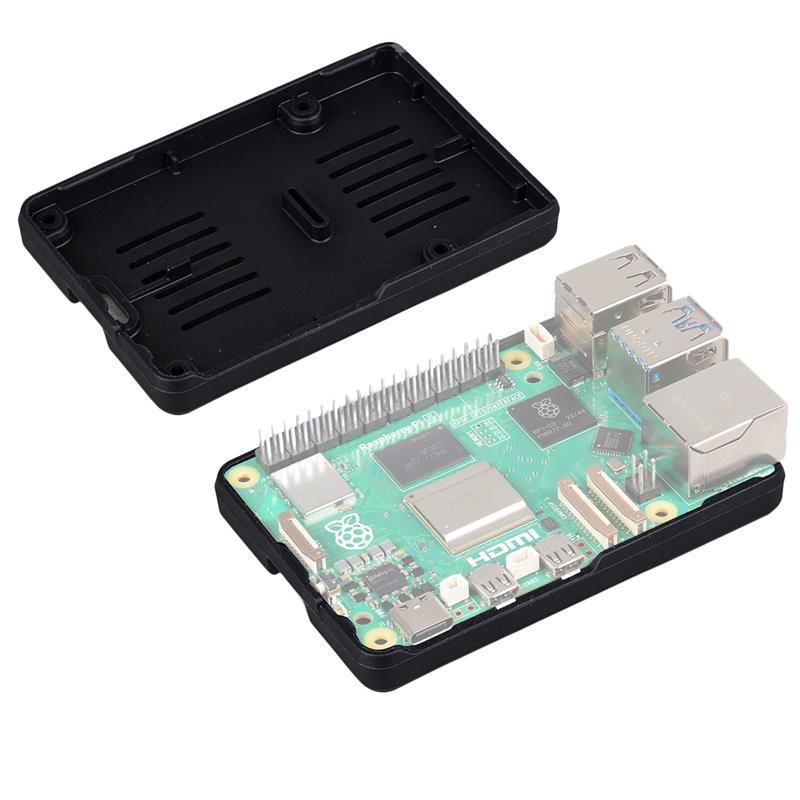
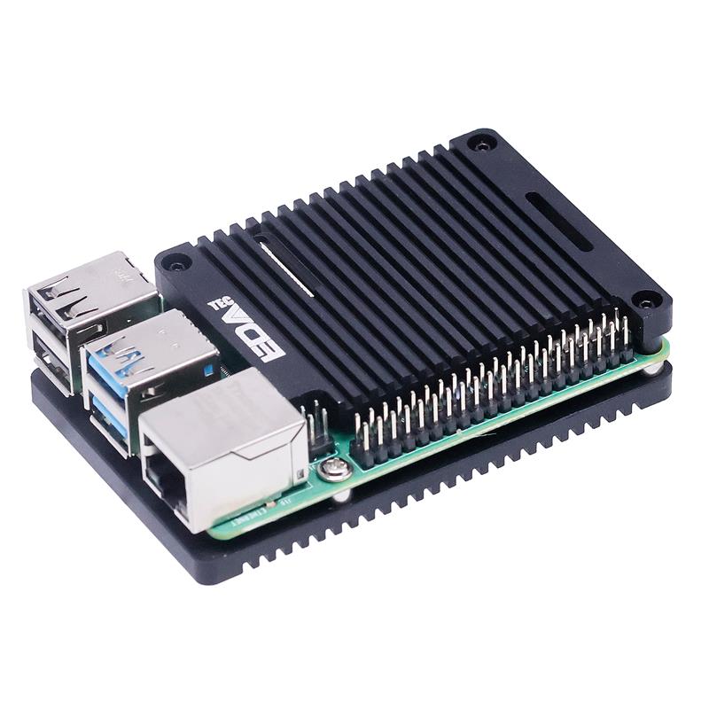
 ▲ OpenPLC 可在 Raspberry Pi 上实现
Running a PLC on a Raspberry Pi (Runtime)
The concept behind developing a PLC using a Raspberry Pi is the implementation of the OpenPLC runtime environment, which has an integrated web server that allows the configuration of runtime parameters. The runtime parameters are aligned with data types and memory registers. Listed below are a few of the parameters:
- X: bit (1-bit)
- B: byte (8-bits)
- W: word (16-bits)
- D: double word (32-bits)
- L: long word (64-bits)
These parameters are created when the structured text (.st) file is compiled and downloaded. The runtime web server is accessed using the Raspberry Pi’s IP address followed by ';' and the port number 8080. Point your mouse to the Wi-Fi icon near the right of the toolbar in the PI desktop environment to find the IP address. The IP address will appear in a popup window.
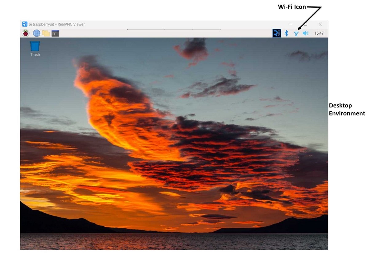
▲ Raspberry Pi Wi-Fi 图标的位置
Prerequisites for OpenPLC on the Raspberry Pi
WiringPi GPIO Library
The OpenPLC runtime needs to access the general-purpose I/O (GPIO) pins. Recent Pi platforms (version 3 and newer) already have this library included, but to verify, open the terminal and type the following:
gpio -vIf the library (command) is ‘not found’, ensure Wi-Fi is enabled and use the following set of commands to install the WiringPi library:
git clone https://github.com/WiringPi/WiringPi.gitThis will copy and create a folder called WiringPi. Change to WiringPi as the current directory:
cd WiringPiThen enter the following command. This will build WiringPi from the source files, sort of like installing:
./buildThis should finish the process, but at this point, run the ‘’ command and see the newly installed details for your Pi platform. It should look much like the image below:
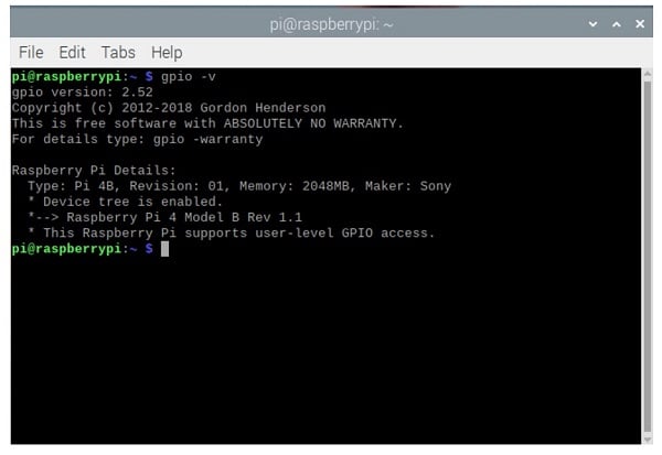 ▲ 成功构建 WiringPi 库
OpenPLC Runtime
If the OpenPLC runtime is not already installed, it follows a similar procedure as before. First, type the command ‘’ to switch back to the main home directorycd
Copy the OpenPLC folder as before with the clone command:
git clone https://github.com/thiagoralves/OpenPLC_v3.gitNow, change to the OpenPLC directory:
cd OpenPLC_v3And finally, install the actual OpenPLC runtime (this takes quite a while, so be patient):
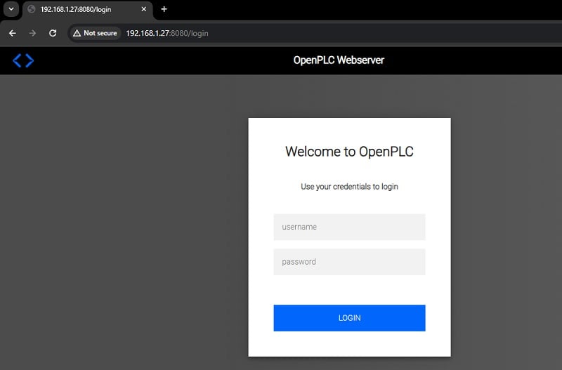
./install.sh rpiWhen this install is finished, go to your home PC web browser and type the IP address of the Raspberry Pi (in my case, it is 192.168.1.27), followed by port 8080, and the runtime login screen should appear:
For more thorough documentation, consult the OpenPLC official website.
https://autonomylogic.com/docs/installing-openplc-runtime-on-linux-systems/
Now that the prerequisite steps are finished on the Pi platform, we can proceed to the wiring and ladder logic programming!
Pin Mapping from the Raspberry Pi to the PLC
nput and output devices like pushbutton switches, actuators, visual indicators, and audible annunciators will be assigned to the appropriate I/O pins of the Raspberry Pi. This project article will consist of a pushbutton switch operating an LED through a very simple ladder diagram PLC program.
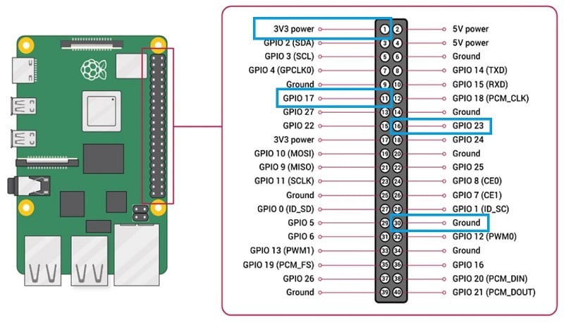
The Raspberry Pi refers to the pins using two different numbering formats. One format labels the pins with appropriate GPIO pin numbers and functions.
In the other format, the 40-pin header is numbered vertically with odd numbers on the left and even numbers on the right. OpenPLC uses the GPIO pins on the left as inputs, so pins 3, 5, 7, 11, and 13 (mapped to GPIO pins 2, 3, 4, 17, and 27) will constitute the input tags IX0.0, IX0.1, IX0.2, IX0.3, IX0.4, and so on.
For the outputs, in a similar fashion, pins 8, 10, 16, 18, and 22 (GPIO 14, 15, 23, 24, and 25) equate to output tags QX0.0, QX0.1, QX0.2, QX0.3, QX0.4, and so on.
Wiring the I/O devices to the Raspberry Pi
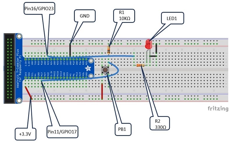
The pushbutton circuit will use a tactile switch with a 10kΩ pulldown resistor. The output indicator circuit consists of a 330Ω resistor wired in series with an LED.
At the simplest level, individual wires can be inserted into the 40-pin header connector and attached to the pushbutton switch and the LED circuit mounted on an external breadboard.
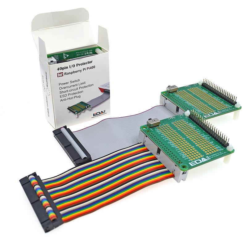
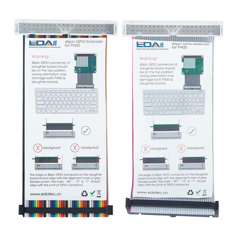
Another approach to attaching the pushbutton switch and the LED circuit to the Raspberry Pi uses an extension board (shown below) that breaks out the Raspberry Pi I/O pins on a T-shaped PCB. The extension board is inserted into an appropriate length/size solderless breadboard, allowing the pushbutton switch, pulldown resistor, and LED circuit to be easily attached to the Raspberry Pi without the bulk of many jumper wires.
 As an additional electrical wiring reference, an electronic circuit schematic diagram is provided.
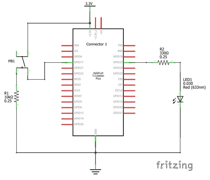
The extension board physically connects to the Raspberry Pi using a flat ribbon cable allowing voltage (+3.3V), ground, and I/O control signals to be electrically attached to the Raspberry Pi 40-pin header connector. The flat cable allows the arrangement of the solderless breadboard to be conveniently placed on the workshop table or lab bench.
The wiring assembly of the breadboard below illustrates the electrical parts wired to the extension board. If an extension breakout board isn’t available, you can use jumper wires to directly connect to +3.3V, GND, pin 11 (GPIO17), and pin 16 (GPIO23) right on the header of the Pi.
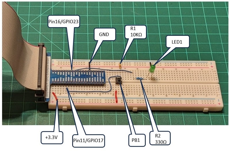
▲ 带扩展板的基于 Raspberry Pi 的 PLC 电路
PLC Software for the Raspberry Pi
The Hello World Ladder Diagram (LD) presented in the Arduino OpenPLC introduction project can be easily modified for the Raspberry Pi controller. The primary modification of the LD involves applying the SBC physical I/O addressing scheme to the Raspberry Pi. The I/O address reflects the body-pin format, not the GPIO designation. With this approach, the assigned tags will ensure that the target pushbutton switch's input and output control signals and the LED circuit will be initiated correctly.
Arduino OpenPLC introduction project:
https://control.com/technical-articles/plc-ladder-logic-on-an-arduino-introduction-to-openplc/
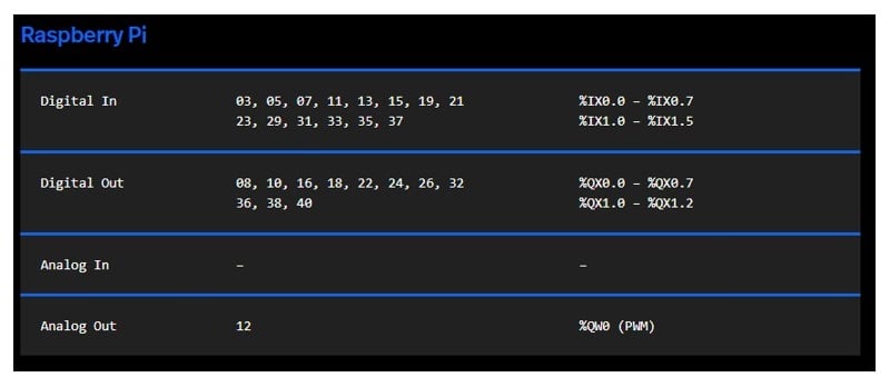
▲ Raspberry Pi 物理寻址
As with the Arduino ladder logic project, the Hello World LD and the Tag listing table are built within the OpenPLC editor.
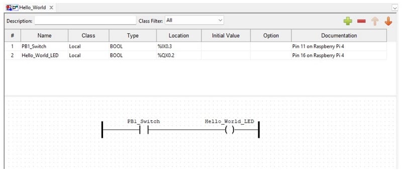
▲ Raspberry Pi “你好世界 ”LD/标记列表表
Adding the Runtime Software and Testing
The final step to the Raspberry Pi OpenPLC project is to upload the runtime software to the SBC. As discussed in the Runtime section, the web server page will need to be accessed. The runtime programming environment will become available by pointing to the Raspberry Pi’s IP address using a web browser.
The default login username and password are both openplc. It is suggested that you change the login credentials to ensure the security of your LD programs.
▲ OpenPLC 网络服务器登录界面
The .st file will be required to run on the Raspberry Pi. By clicking the orange down arrow icon on the OpenPLC editor’s taskbar, the .st file will be stored in a designated folder created for the initial project.
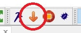
▲ OpenPLC Runtime .st 文件下载按钮
Back in the webserver, click on the Hardware button, select the Raspberry Pi as the hardware layer, and Save changes.
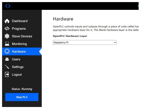
▲ 选择 Raspberry Pi 硬件
To upload the .st file, click on the Programs button on the left side of the OpenPLC web server panel.
A window will open where the .st file (program) can be uploaded to the web server. Click the Choose File button, select the Hello World.st file, and then click Upload Program.
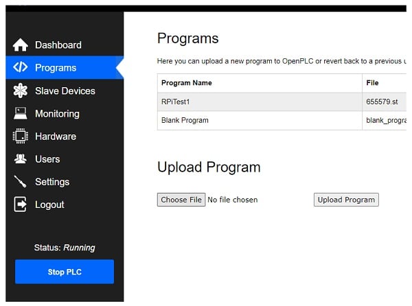
▲ 选择并上传 .st 文件
The compilation process of converting the .st file to a C++ program will be visible. The Hello World program will be displayed on a table after completing the upload/conversion process.
With the Hello World program uploaded to the Raspberry Pi, click the Dashboard button with the mouse at the bottom of the web server’s window. Click the Start PLC button on the left side of the panel. The execution process of the program will be visible in the window.
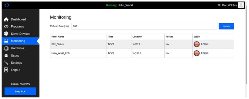
▲ 用于 Raspberry Pi 的 “Hello World ”监控仪表板
The status of the pushbutton switch and the LED can be observed using the Monitor. Click the Monitor button with the mouse to observe the actions of the pushbutton switch and the LED. With each press of the pushbutton, the LEDs will switch from red to green. The monitor can be a diagnostic human-machine interface (HMI) tool to virtually watch the Raspberry Pi PLC I/O's physical operation.
This video clip illustrates the Raspberry Pi PLC in operation. With an understanding of the runtime environment and accessing the OpenPLC web server page, a variety of PLC-control applications can be implemented on a Raspberry Pi.
Original address: https://control.com/technical-articles/turn-a-raspberry-pi-into-a-plc-using-openplc/


