Select Region/Language
EN CN

ED-SBC2300

ED-SBC2300

ED-SBC2300 is a compact, feature-rich industrial SBC based on Raspberry Pi CM4.

Key Featured
  • Compact Mini-ITX form factor based on Raspberry Pi CM4.
  • 1.5GHz quad-core ARM Cortex-A72 processor.
  • Supports up to 8GB RAM and 32GB eMMC, with Micro SD and mSATA expansion.
  • Dual display support with HDMI and LVDS or eDP.
  • 2 USB 3.0 and 5 USB 2.0 ports, plus 2 RS485 and 7 RS232 serial ports.
  • Integrated dual-band Wi-Fi, Bluetooth, and optional 4G LTE.
  • Wide voltage input range and PoE support.
  • Enhanced security with RTC, EEPROM, and crypto authentication.
  • Runs various Raspberry Pi OS versions.
  • Comprehensive rear I/O, including HDMI 2.1 and multiple USB ports.
  • Customizable expansion options with GPIO and front panel connectors.
  • Optional display interfaces with adjustable settings.

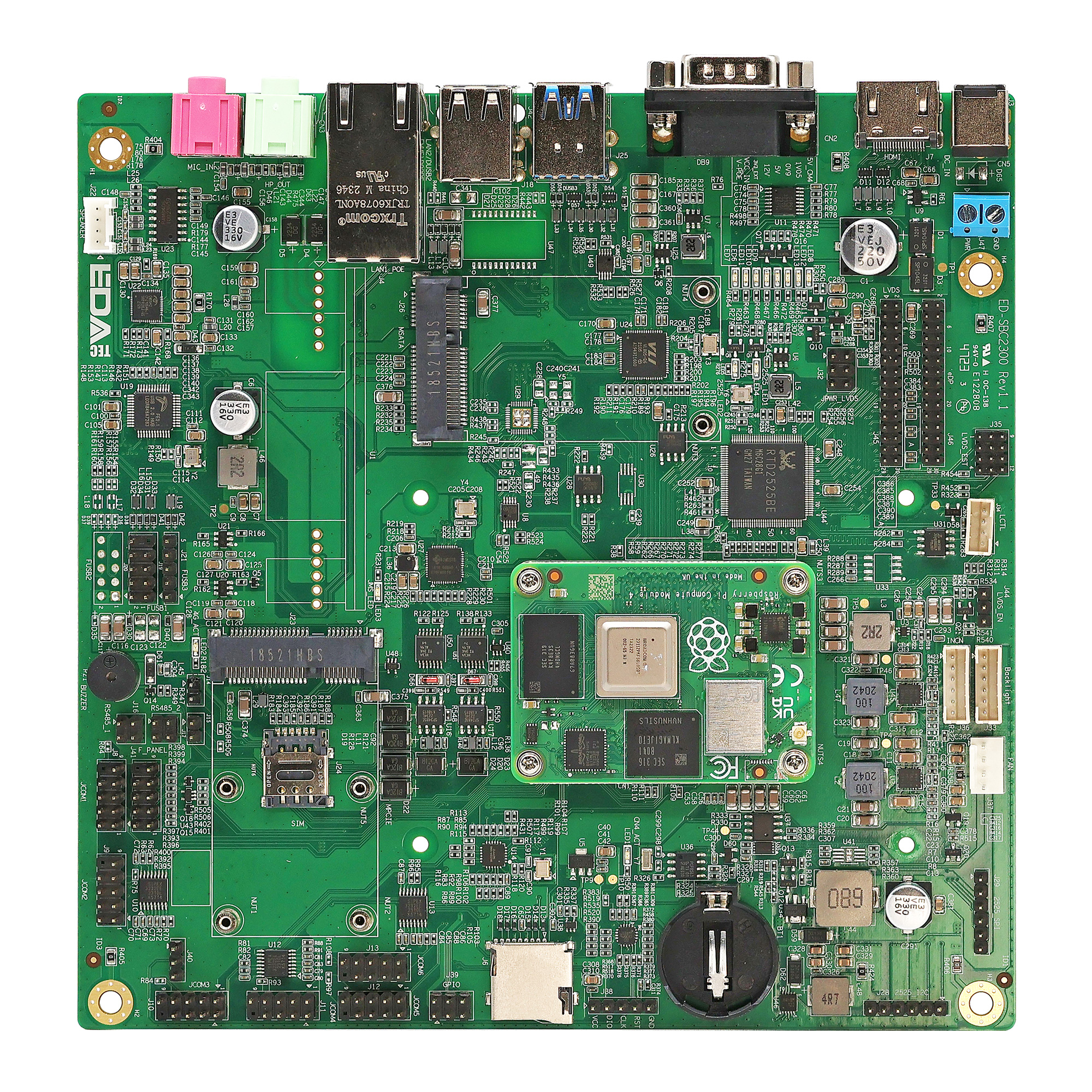
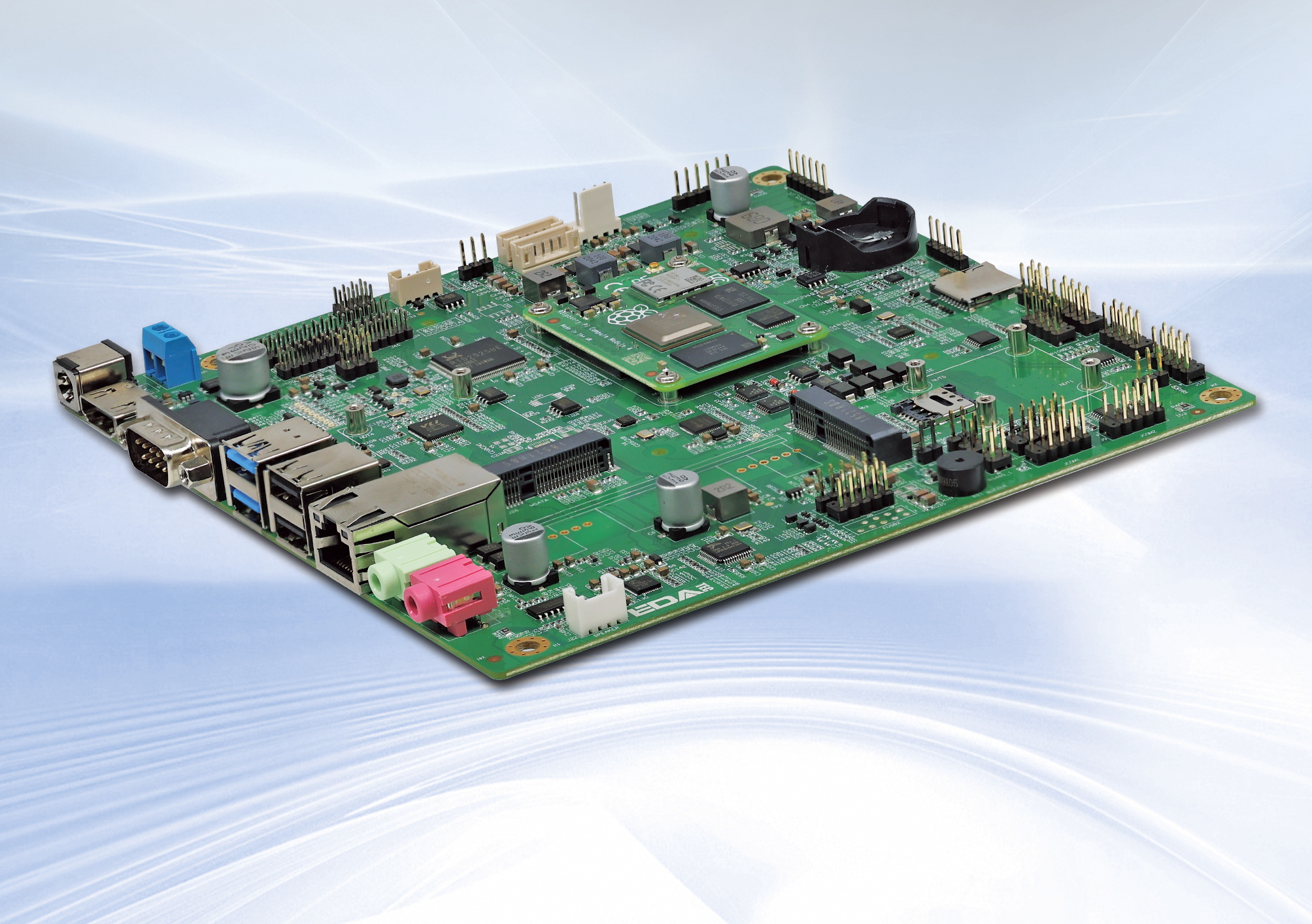
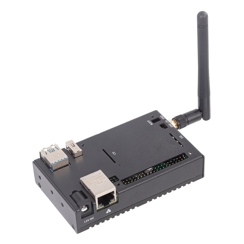
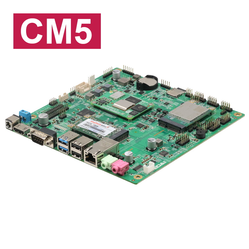
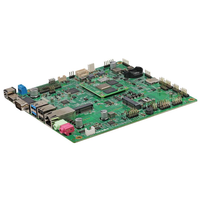
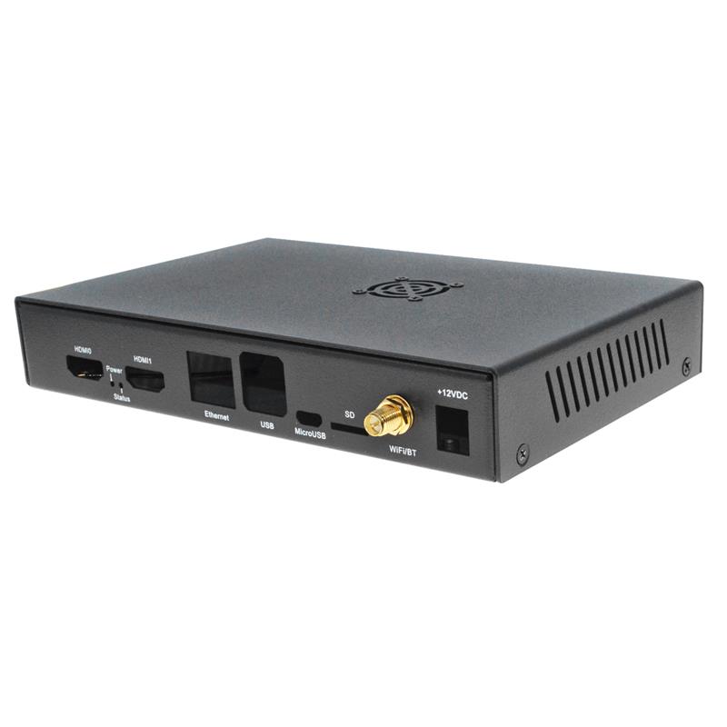
The ED-SBC2300 is a Mini-ITX industrial computer motherboard developed by Shanghai Jingheng, based on the Raspberry Pi CM4. This fanless design motherboard is an excellent choice for industrial applications where space is at a premium but performance is still required. It is powered by a Broadcom BCM2711, a quad-core Cortex-A72 (ARM v8) 64-bit System on Chip (SoC) that operates at a speed of 1.5GHz, ensuring robust processing capabilities. The board can be configured with up to 8GB of LPDDR4 RAM and 32GB of eMMC storage, providing ample memory for running demanding applications. Additionally, it supports storage expansion via a Micro SD card and an mSATA SSD.

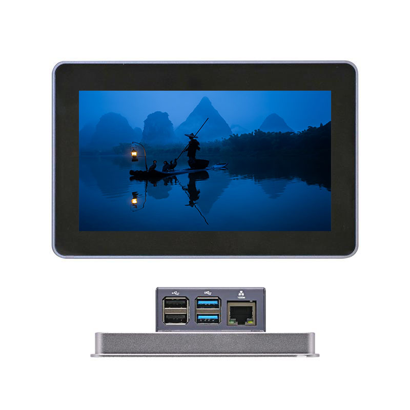
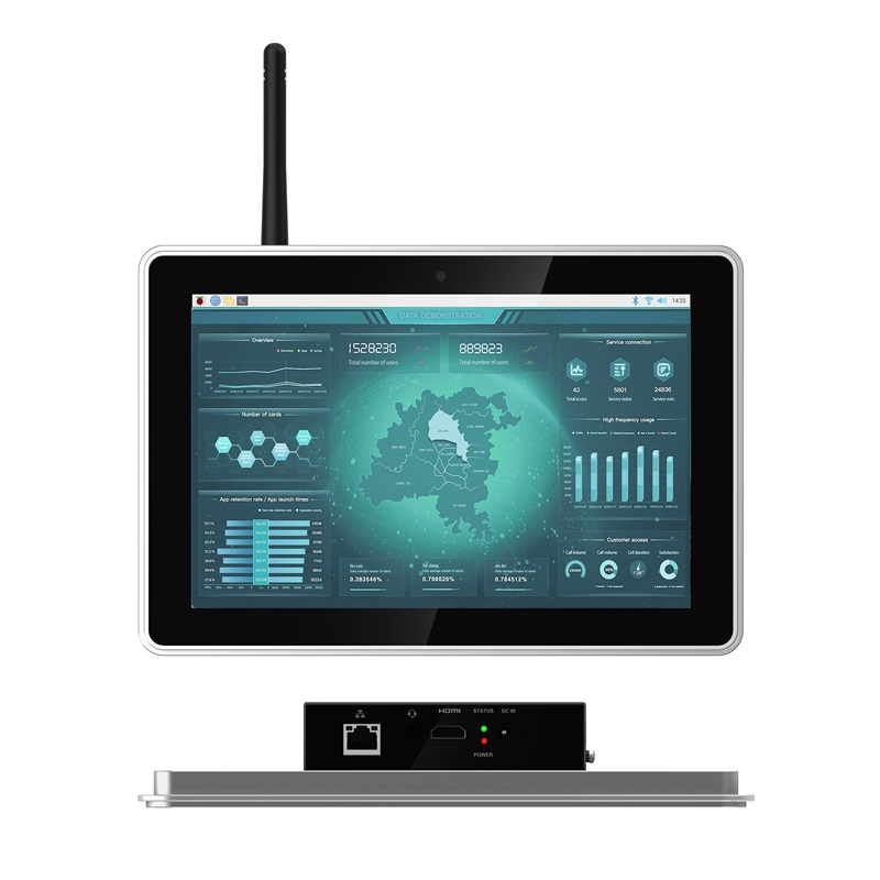
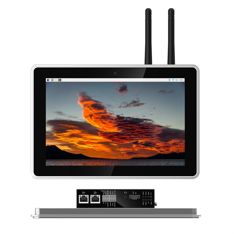
The ED-SBC2300 offers a range of display options, supporting both HDMI+LVDS and HDMI+eDP configurations for dual displays, including touchscreen capabilities. It also has a LAN port that supports speeds up to 1Gbps, with the option for dual LANs, and includes 2 USB 3.0 ports and 5 USB 2.0 ports for a variety of connectivity needs. The board also features 2 RS485 and 7 RS232 serial ports, making it suitable for applications that require serial communications.

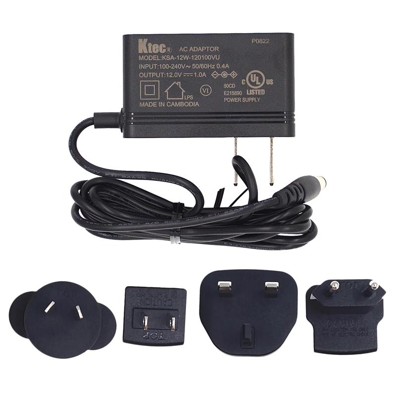
For wireless connectivity, the ED-SBC2300 supports 2.4GHz and 5GHz dual-band Wi-Fi, Bluetooth, and even 4G LTE, making it a versatile choice for IoT and remote applications. The power input range is wide, accepting DC voltage from 9V to 36V, and it can also be powered via PoE (Power over Ethernet), providing flexibility in power supply options.

The ED-SBC2300 also includes an integrated Real-Time Clock (RTC), EEPROM, and crypto authentication, which are essential for maintaining system time and ensuring the security of the device. The board's specifications are rounded out with support for various operating systems, including 32-bit and 64-bit versions of Raspberry Pi OS, both Desktop and Lite editions.

In terms of physical connectivity, the ED-SBC2300 offers a comprehensive set of I/O options on its rear panel, including a DC IN jack with reverse polarity and overvoltage protection, an HDMI port compatible with HDMI 2.1 standard supporting 4K at 60Hz, and multiple USB ports as mentioned earlier. It also has optional audio interfaces, a Micro SD card slot, and a Micro SIM card slot for wireless communication.

Expansion I/O options include additional USB 2.0 ports, RS232 and RS485 serial ports, GPIO pins for custom functions, and a front panel port for power and reset buttons, as well as HDD and power indicators. The board also supports optional LVDS and eDP display interfaces, with additional pins for adjusting display settings such as resolution and brightness.

Overall, the ED-SBC2300 is a high-performance, feature-rich industrial motherboard designed for a wide range of applications, from industrial automation to digital signage, and is well-equipped to handle the demands of modern embedded systems.

System Diagram
image-20240903134613582
Specification
System
CPUBroadcom BCM2711, quad core Cortex-A72 (ARM v8) 64-bit SoC @ 1.5GHz
VPUH.265(HEVC), up to 4Kp60 decode
H.264, up to 1080p60 decode, 1080p30 encode
GPUOpenGL ES 3.1 & Vulkan 1.0
MemoryOptions for 1GB, 2GB, 4GB, 8GB LPDDR4-3200 SDRAM
StorageOptions for 8GB, 16GB, 32GB eMMC storageMicro SD card (user storage expansion) mSATA SSD (optional)
Software
Operating SystemRaspberry Pi OS (Desktop) 32-bit
Raspberry Pi OS (Lite) 32-bit
Raspberry Pi OS (Desktop) 64-bit
Raspberry Pi OS (Lite) 64-bit
Rear I/O
Power1 x DC IN, DC Jack connector (2-Pin 3.5mm pitch phoenix terminal is optional).
It supports 9V~36V input.
HDMI1 x HDMI port, type A connector, which is compatibles with HDMI 2.0 standard and supports 4K 60Hz.
COM1 x RS232 port, DB9 male connector, using the 2, 3 and 5 pins, the corresponding signal is defined as RX/TX/GND.
USB 3.02 x USB 3.0 ports, type A connector, support up to 5Gbps.
USB2.0/1000M Ethernet Choose one between 2 x USB 2.0 ports and 1 x 1000M Ethernet port.
  • 2 x USB 2.0 ports, type A connector, which support up to 480Mbps.
  • 1 x adaptive 10/100/1000M ethernet port, RJ45 connector.It can be used to access the network.
Different ports can be selected according to actual application.
  • ED-SBC2310: 2 x USB 2.0
  • ED-SBC2311: 1 x 1000M Ethernet
  • ED-SBC2320: 2 x USB 2.0
  • ED-SBC2321: 1 x 1000M Ethernet
1000M Ethernet1 x adaptive 10/100/1000M ethernet port, RJ45 connector. It can be used to access the network.
LINE OUT (optional)1 x Audio Output, 3.5mm audio jack connector(green), stereo audio output.
Note: Only ED-SBC2320 and ED-SBC2321 contains this interface.
MIC IN (optional)1 x MIC Input, 3.5mm audio jack connector(red), which can connect to microphone.
Note: Only ED-SBC2320 and ED-SBC2321 contains this interface.
SD Card Slot1 x Micro SD card slot, which is used to install SD card for storing user data.
SIM Card Slot1 x Micro SIM card slot, which is used to install SIM card for getting 4G signal.
Expansion I/O
Power Supply1 x power port, 2-Pin 5mm pitch connector, reserving to provide power supply for motherboard. It supports 9V~36V input, the signal is defined as VIN+/GND.
Speaker (optional)1 x PA output, 4-Pin 2.0mm pitch WTB connector, dual channel stereo audio output. It can be extended to connect two 4Ω 3W stereo speakers, these pins are defined as R+/R-/L+/L-.
Note: Only ED-SBC2320 and ED-SBC2321 contains this interface.
USB 2.03 x USB 2.0 ports or 5 x USB 2.0 ports, different numbers of USB 2.0 ports can be selected according to actual application.
  • ED-SBC2310 and ED-SBC2320: 3 x USB 2.0 ports (include USB1 and USB3)
  • ED-SBC2311 and ED-SBC2321: 5 x USB 2.0 ports (include USB1, USB2 and USB3)
  • USB1, USB2 and USB3 are the silkscreens of the USB 2.0 ports on the motherboard, corresponding to J19, J20 and J21. The ports and functions are defined as follows:
    • USB1 and USB2 respectively contain 2 x USB 2.0 ports, 2x5(9)-Pin 2.54mm pitch Pin Header. These pins are defined as +5V/+5V/USB1 Date-/USB2 Date-/USB1Date+/USB2Date+/GND/GND/NC.
    • USB3 contains 1 x USB 2.0 port, 5-Pin 2.54mm pitch Pin Header, these pins are defined as +5V/Date-/Date+/GND/NC.
Note: Only ED-SBC2320 and ED-SBC2321 contains this interface.
RS2326 x RS232, 2x5(9)-Pin 2.54mm pitch Pin Header, which support to expand the RS232 ports. The single signal is defined as DCD/RXD/TXD/DTR/GND/DSR/RTS/CTS/R1.
RS4852 x RS485, 2x2-Pin 2.54mm pitch Pin Header, which support to expand the RS485 port and the single signal is defined as A/B. A 120R jumper resistor is reserved between A and B of RS485 line. The jumper cap can be inserted to enable the jumper resistor.
6-Pin GPIO1 x GPIO Pin Header, 2x3-Pin 2.54mm pitch Pin Header, which uses to lead out the expansion GPIO ports. User can customize the function according to actual application.The pins are defined as VCC/GND/4xGPIO.
mSATA1 x mSATA port, Mini PCIe connector, which supports to connect mSATA*2 SSD.
Front Panel (Buttons/Indicators)1 x Front Panel port, 2x5-Pin 2.54mm pitch Pin Header, reserving to connect power button, reset button, HDD indicator and power indicator.
The pins are defined as HDD LED+/HDD LED-/PWR LED+/PWR LED-/RESET-SW/GND/GND/POWER-SW/GND/NC.
Auto-boot after powering on1 x Auto-boot port, 3-Pin 2.54mm pitch Pin Header, which can set whether to enable the auto-boot after powering on by choosing to connect different pins.
The pins and functions are defined as follows:
  • Pin 1-2(Default): Disable
  • Pin 2-3: Enable
LVDS Display (optional)1 x LVDS Display Port, 2x15-Pin 2.54mm pitch Pin Header. It is reserved to connect LVDS display, and supports up to 1080p 60Hz.
Note: Only ED-SBC2320 and ED-SBC2321 contains this interface.
Voltage Setting of LVDS Display (optional)1 x Voltage Setting port of LVDS display, 2x15-Pin 2.54mm pitch Pin Header. We can set different voltage by choosing to connect different pins, which meets the power supply requirements of various LVDS display.
The pins and functions are defined as follows:
  • Pin 1-2(Default): +3.3V
  • Pin 3-4: +5V
  • Pin 5-6: +12V
Note: Only ED-SBC2320 and ED-SBC2321 contains this interface.
Enabling Setting of LVDS Display (optional)1 x Enabling Setting port of LVDS display, 2x15-Pin 2.54mm pitch Pin Header. We can open or close the LVDS display by choosing to connect different pins. The pins and functions are defined as follows:
  • Pin 1-2: Open LVDS display
  • Pin 2-3(Default): Close LVDS display
Note: Only ED-SBC2320 and ED-SBC2321 contains this interface.
Resolution Setting of LVDS Output (optional)1 x Resolution Setting port of LVDS Output, 3x4-Pin 2.0mm pitch Pin Header. We can select screens of different sizes and resolutions by setting the level of pins.
Available screens: 12.1-inch (800x600), 15-inch (1024x768), 15.6-inch (1920x1080), 17-inch (1280x1024) and 21.5-inch (1920x1080).
Note: Only ED-SBC2320 and ED-SBC2321 contains this interface.
Brightness Control of LVDS Display (optional)1 x Brightness Control port of LVDS display, 4-Pin 2.0mm pitch WTB connector. We can adjust brightness of LVDS display by choosing to connect different pins. The pins and functions are defined as follows:
  • Pin 1-2:Brightness increase
  • Pin 2-3:Brightness decrease
  • Pin 2-4:Brightness enable/disable
Note: Only ED-SBC2320 and ED-SBC2321 contains this interface.
Backlight Power (optional)1 x Backlight Power port, 6-Pin 2.0mm pitch WTB connector, which provides 12V power supply, PWM enable and PWM adjustment for backlight of LVDS display.
The pins are defined as +12V/+12V/GND/GND/LVDS_BKL_EN/LVDS_BKL_CTRL.
Note: Only ED-SBC2320 and ED-SBC2321 contains this interface.
Backlight Control (optional)1 x Backlight Control port, 6-Pin 2.0mm pitch WTB connector, which integrates on-board backlight driver circuit, supports enabling and adjustment of backlight brightness.
The pins are defined as Vdc-/Vdc-/Vdc+/Vdc+/Vdc-/Vdc-.
Note: Only ED-SBC2320 and ED-SBC2321 contains this interface.
Expansion Performance
EEPROMSupports 4K byte storage and improves the ease of use of device.
Crypto AuthenticationIt can be matched to realize the required upper layer application and improves the security of device.
RTCEnsure that the system clock is not affected by device power-off.
Note: A CR2032 battery is provided by default in China.
BuzzerA tip or an abnormity can be configurated according to actual application, which realizes the alarm function.
Electrical Characteristics
Input Voltage9V ~ 36V DC
Power Consumption60W (Max)
Mechanical Characteristics
Dimensions170mm x 170mm (W x D)
Weight100g
Wireless
Wi-Fi/Bluetooth (optional)2.4GHz and 5GHz dual-band Wi-Fi
  • 2.4GHz and 5GHz dual-band Wi-Fi2.4GHz Wi-Fi: Compatible with IEEE 802.11 b/g/n.
  • 5GHz Wi-Fi: Compatible with IEEE 802.11 a/n/ac.
  • Bluetooth 5.0, compatible with 2402MHz ~ 2480MHz frequency.
4G (optional)Connect with various 4G LTE modules through the Mini PCIe interface.
  • EC20-CE Module (China/India)
    • LTE FDD: B1/B3
    • LTE TDD: B38/B39/B40/B41
    • TDSCDMA: B34/B39
    • WCDMA: B1
    • CDMA 1x/EVDO: BC0
    • GSM: 900/1800MHz
  • EC25-AFX Module (North America)
    • LTE FDD: B2/B4/B5/B12/B13/B14/B66/B71
    • WCDMA: B2/B4/B5
    • GSM/EDGE
  • EC25-AUX Module (Latin America/Australia/New Zealand)
    • LTE FDD: B1/B2/B3/B4/B5/B7/B8/B28
    • LTE TDD: B40
    • WCDMA: B1/B2/B4/B5/B8
    • GSM/EDGE: B2/B3/B5/B8
  • EC25-EUX Module (Europe/Middle East/Africa/Thailand)
    • LTE FDD: B1/B3/B7/B8/B20/B28A
    • LTE TDD: B38/B40/B41
    • WCDMA: B1/B8
    • GSM/EDGE: B3/B8
Environmental & Regulatory
Operating Temperature-25°C ~ 50°C
Storage Temperature-25°C ~ 60°C
Ambient Humidity5% ~ 95% (non-condensing)
CertificationsFCC
FCC 47 CFR Part 15 Subpart B
CE
EN IEC 62368-1/EN IEC 62311/EN IEC 61000-3-2/EN IEC 61000-3-3
EN 55032/EN 55035
EN 301 489-1/EN 301 489-3/EN 301 489-17/EN 301 489-52
EN 301 328/EN 301 440/EN 301 511/EN 301 908-1/EN 301 908-2
Mechanicals

Unit: mm

image-20240903135117567
Ordering Code
image-20240903135214432
Docs
Type Title Publish Time
Datasheet ED-SBC2300 Datasheet 2024-04-10
Manual ED-SBC2300 User Manual 2024-04-10
OS ED-SBC2300 Installing OS 2024-04-10
Related Products
ED-IPC3020
  • M.2 SSD
  • Stereo Audio
  • PoE
  • RS232
  • RS485

EDATEC

Started in 2017, EDATEC has been certified as one of the global design partners of Raspberry Pi since 2018, providing Raspberry Pi based industrial computers design and manufacturing services for global customers.

  • Building 29, No. 1661, Jialuo Road, Jiading District, Shanghai.
  • CN: +86-18217351262 (Iris Zhou)
    US: +1 859-653-0800 (Randall Restle)
  • support@edatec.cn
Submit Your Message

INFO

By submitting, you agree to EDATEC's policies

Please enter the verification code

captcha
0.705942s