


 En
En


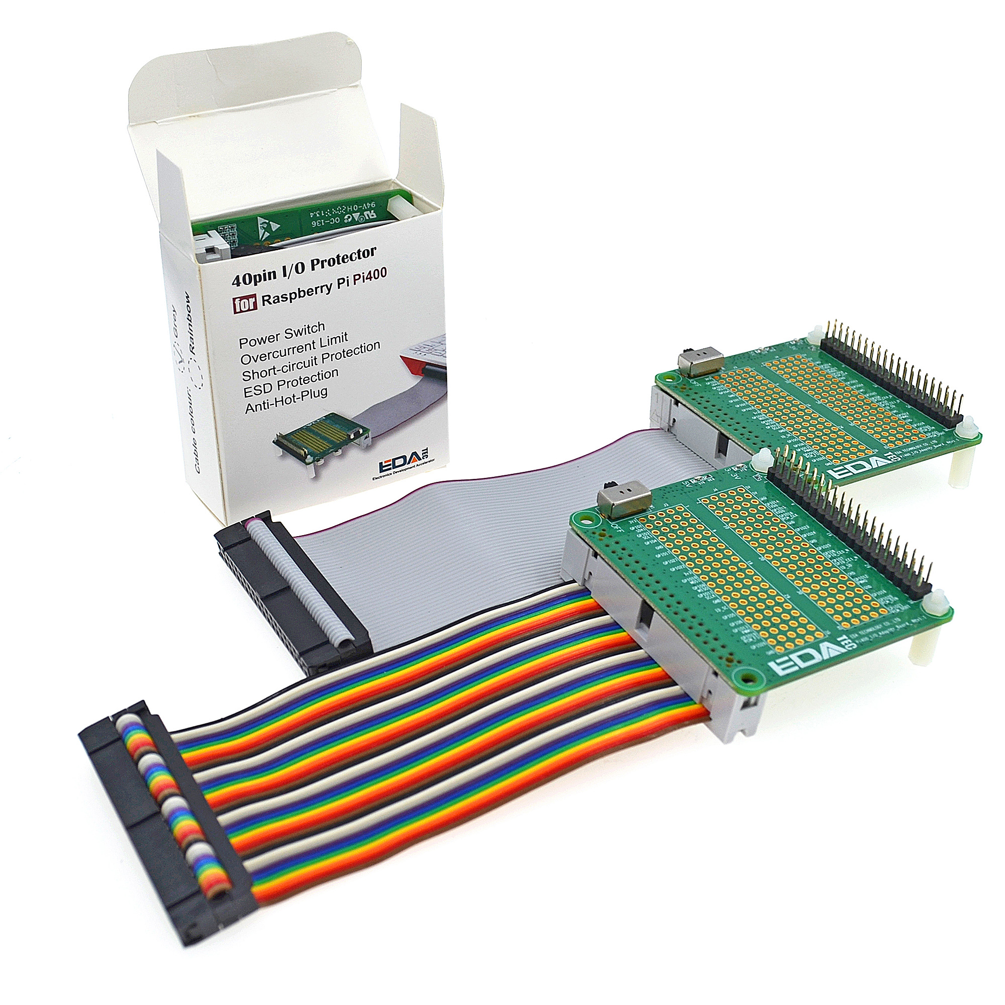
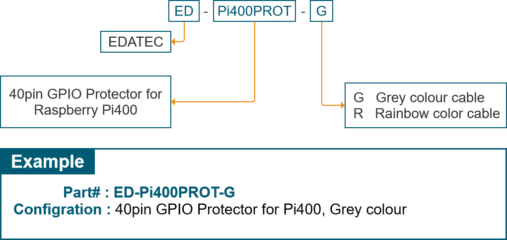
Protect Raspberry Pi400 by ESD immunity IC, Tiny Switch and Over current limit circuit.
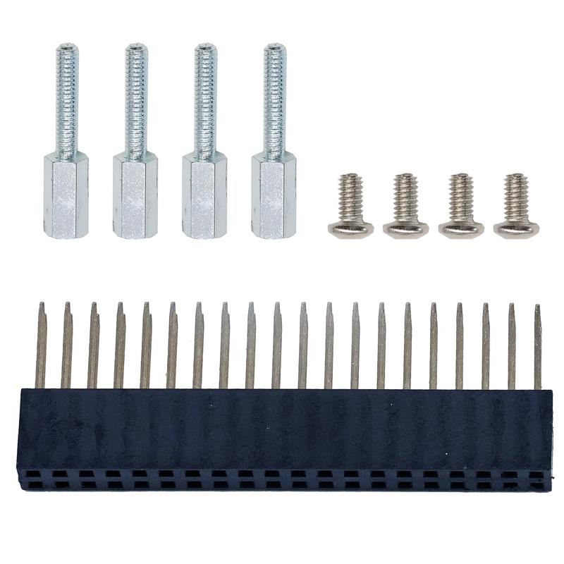
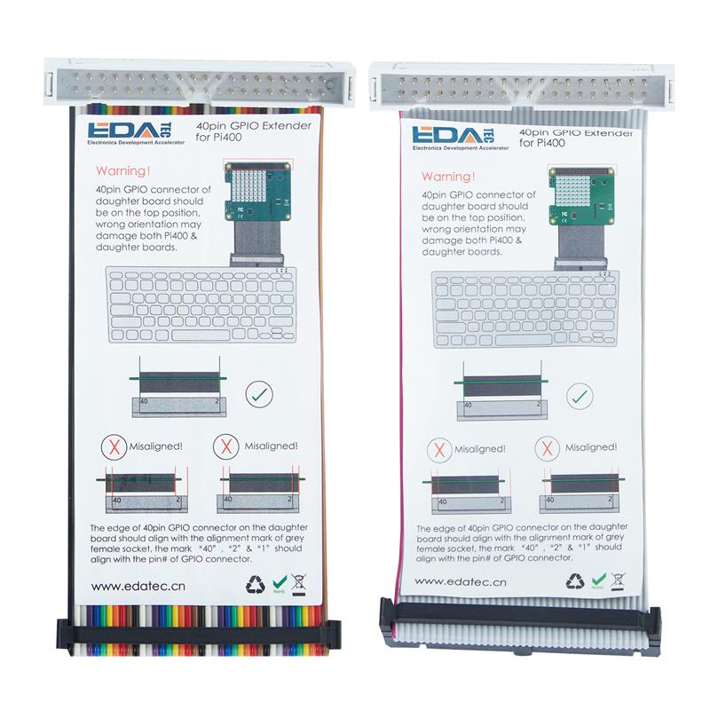
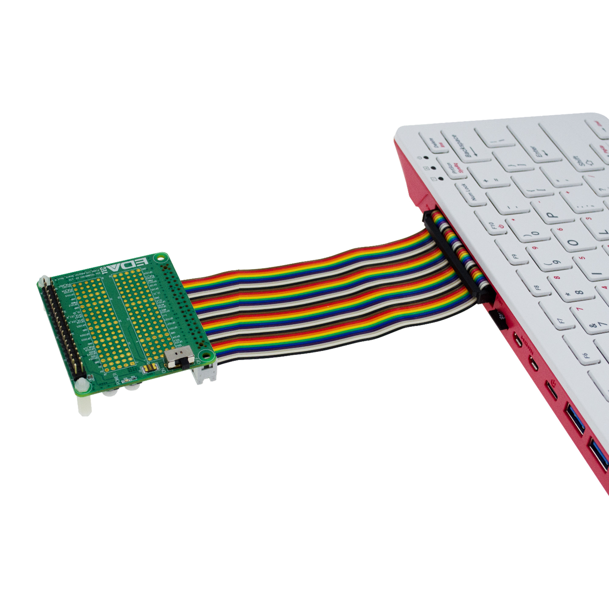
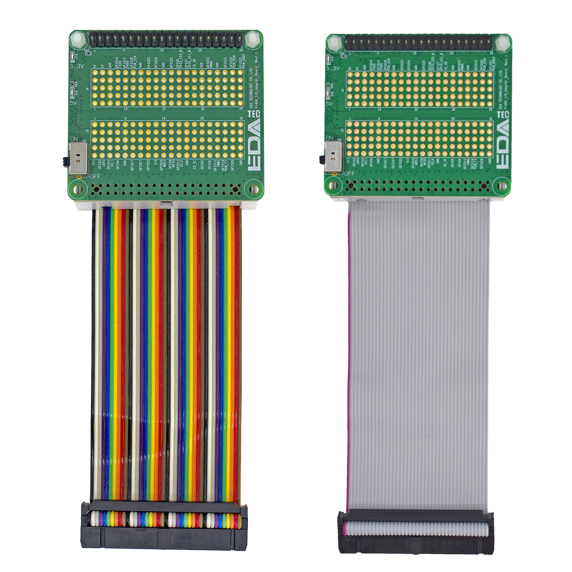
40pin GPIO Protector are made of a 40pin ribbon cable & a circuit board, the 40pin ribbon cable is to lead 40pin GPIO signals from Pi 400 to the circuit board, the circuit board provides a series of functions to protect Pi 400 computer.
A tiny switch at the left board edge is to control +5V & +3.3V power supply for the daughter board, the user can switch off the daughter board by switching the tiny switch at “OFF” position, when the user wants to install the daughter board on the 40pin connector, he/she doesn’t have to shut down Pi 400, just need to switch off the power of 40pin GPIO Protector, it protects Pi400 from damage due to hot plug.