


 En
En

Sandeep Mistry, Principal Software Engineer with our friends at Arm, takes us through a neat way to apply audio noise suppression to a microphone input on our brand new Raspberry Pi Pico 2.
Machine Learning (ML) technologies have revolutionised the way many software applications are developed. Application developers now curate datasets with numerous example inputs and outputs for a desired system, then use these datasets to train ML models. During training, the ML model learns patterns from the inputs and outputs. Trained models are then deployed to devices which perform inferencing on inputs from the real world and use the ML model’s predicted output to perform one or more actions.
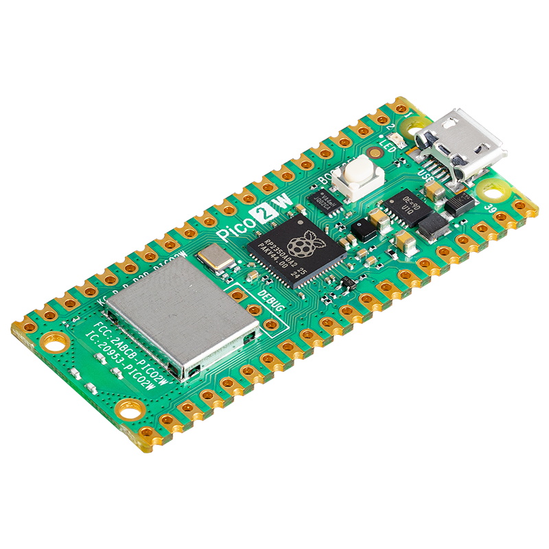
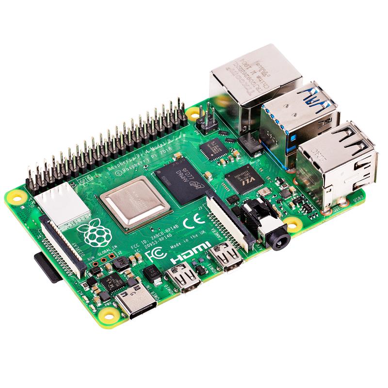
Smaller ML models that require kilobytes of memory can be deployed to microcontroller-based devices, like the Arm Cortex-M33–based Raspberry Pi RP2350 microcontroller used in the new Pico 2 board. Deploying ML models to microcontrollers enables systems to have lower latency, as the data is processed on devices close to the input data source.
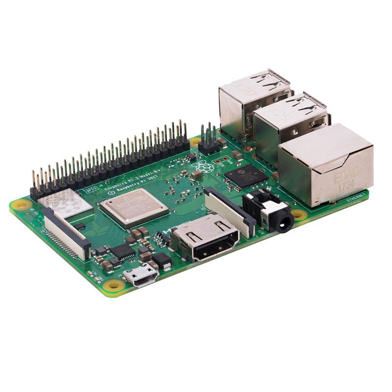
This blog will delve into how an existing ML-based audio noise suppression algorithm can be deployed to Raspberry Pi’s RP2350 microcontroller used in the new Pico 2 board. RP2350’s dual-core Arm Cortex-M33 CPU enables application developers to deploy more compute-intensive applications that exceed the performance capabilities of the RP2040 microcontroller used in the original Raspberry Pi Pico board.
The algorithm will then be integrated into the USB microphone application I developed for the original Pico board. The original application captured data from a digital pulse-density modulation (PDM) microphone and processed it i
Arm Cortex-M33:https://developer.arm.com/Processors/Cortex-M33
Pico 2:https://www.raspberrypi.com/products/raspberry-pi-pico-2/
RP2350:https://www.raspberrypi.com/products/RP2350/
USB microphone application developed for original Pico board:https://www.hackster.io/sandeep-mistry/create-a-usb-microphone-with-the-raspberry-pi-pico-cc9bd5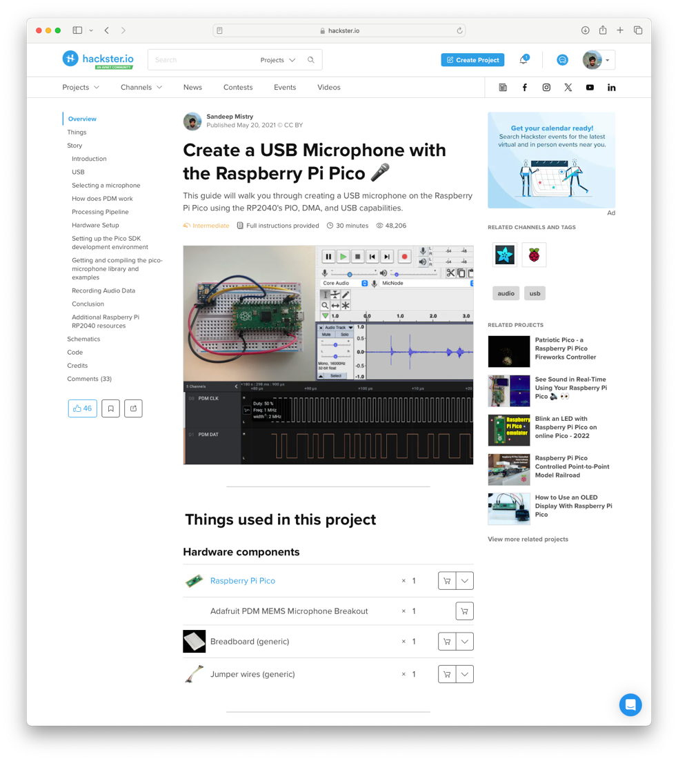
Screenshot of Create a USB Microphone with the Raspberry Pi Pico guide on Hackster.io
Background on the algorithm
In 2018, Jean-Marc Valin published a paper on A Hybrid DSP/Deep Learning Approach to Real-Time Full-Band Speech Enhancement. The paper covers how a recurrent neural network (RNN)-based ML model can be used to suppress noise in an audio source. If you’re interested in learning more about the algorithm, read Jean-Marc’s RNNoise: Learning Noise Suppression page. The page covers details of the algorithm and includes interactive examples. Source code for the project is available in the RNNoise Git repository.
RNNoise:https://jmvalin.ca/demo/rnnoise/
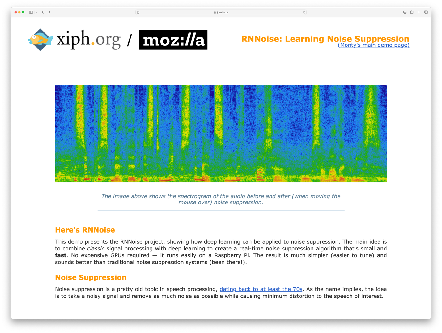
Screenshot of RNNoise: Learning Noise Suppression page
At a high level, the algorithm extracts 42 features from 10 milliseconds of a 48 kHz audio source by splitting the signal into 22 frequency bands.
Screenshot: “Defining the problem” section of the RNNoise: Learning Noise Suppression page
The 42 features are then used as the input to a neural network which calculates gains for the 22 frequency bands. The calculated gains can then be applied to the original audio signal to produce a denoised version. The neural network also outputs a “voice activity detection” output, which indicates the predicted confidence level of a voice being present in the input signal, with values between 0 and 1.
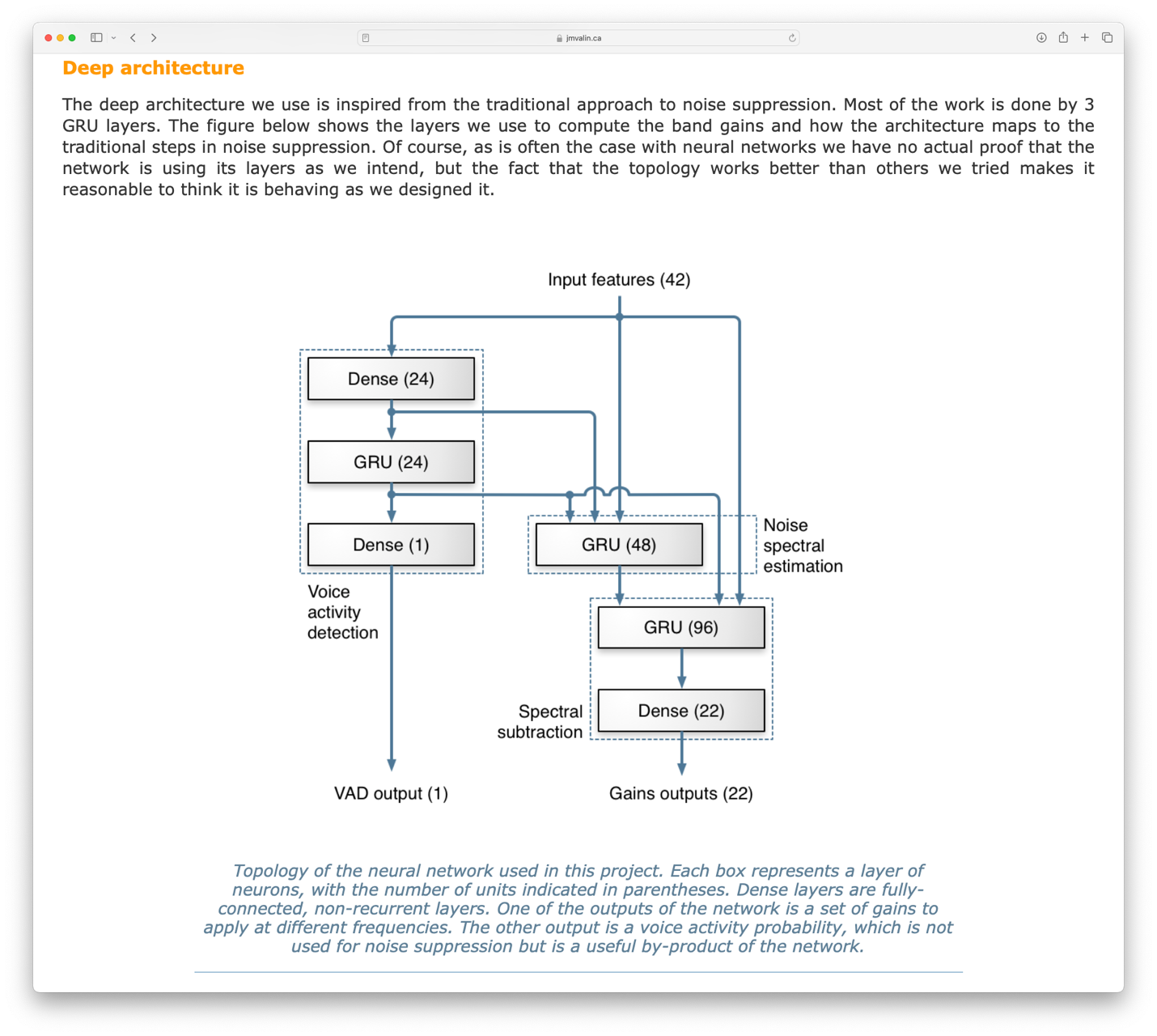
Screenshot: “Deep architecture” section of the RNNoise: Learning Noise Suppression page
Porting and benchmarking the algorithm
The original C code of the RNNoise project can be integrated into a CMake project that uses the Raspberry Pi Pico SDK. All source code for the porting can be found on the rnnoise-examples-for-pico-2 repository on GitHub. A new CMake library target was created with the , , , , , and files from v0.1.1 of the RNNoise project.celt_lpc.cdenoise.ckiss_fft.cpitch.crnn.crnn_data.c
Some minor modifications were made to to use single precision floating point calculations in the biquad function, as well as to use and instead of and functions.denoise.clog10f(…)sqrtf(…)log10(…)sqrt(…)
The library can then be integrated into a benchmarking application that calls the function to initialize the model before measuring how long the function takes to process 480 samples.rrnoise_create(…)rnnoise_process_frame(…)
This benchmarking application can be deployed to a Raspberry Pi Pico 1 or Pico 2 board by first following Sections 2 and 9 of the “Getting started with Raspberry Pi Pico” C/C++ SDK guide, then running the following commands to build the .uf2 application to deploy to the board:
git clone --recurse-submodules \
https://github.com/ArmDeveloperEcosystem/rnnoise-examples-for-pico-2.git
cd rnnoise-examples-for-pico-2
mkdir build
cmake ... -DPICO_BOARD=pico2
make rnnoise-benchmark
After compiling, the file can be deployed to the board by holding down the board’s white BOOTSEL button while plugging in the USB cable to your computer and copying the .uf2 file to the Pico’s USB disk.examples/benchmark/rnnoise-benchmark.uf2
Here are results of the benchmark on a Pico 1 and Pico 2 board:
| Pico (RP2040) Cortex-M0+ @ 125 MHz | Pico 2 (RP2350) Cortex-M33 @ 150 MHz | |
|---|---|---|
| rnnnoise_process_frame(...) | 372,644 microseconds | 22,093 microseconds |
The original Pico 1 takes approximately 372.6 milliseconds vs the new Pico 2’s 22.1 milliseconds: this is a 16.87x speed-up between boards.
Modifying the algorithm for 16 kHz audio
For the board to process 480 samples of audio at a sample rate of 48 kHz it must take less than 0.01 seconds (480 / 48,000) or 10 milliseconds to complete the function . Our benchmark result for Pico 2 takes 22.1 milliseconds and is not fast enough for 48 kHz audio, but it is fast enough to process audio with a sample rate of 16 kHz requiring the audio be processed in under 30 milliseconds.rnnoise_process_frame(…)
The variable in can be easily modified to adjust the algorithm for processing 16 kHz data. This variable controls the start range used in 22 frequency bands. It can be adjusted by multiplying the original values by 3, as 16 kHz audio takes 3 times longer to collect samples than 48 kHz audio, and setting the maximum starting position to 120.eband5msdenoise.c
Here’s the original value:
static const opus_int16 eband5ms[] = {/*0 200 400 600 800 1k 1.2 1.4 1.6 2k 2.4 2.8 3.2 4k 4.8 5.6 6.8 8k 9.6 12k 15.6 20k*/0, 1, 2, 3, 4, 5, 6, 7, 8, 10, 12, 14, 16, 20, 24, 28, 34, 40, 48, 60, 78, 100};
And the modified value to use with 16 kHz audio:
static const opus_int16 eband5ms[] = {/*0 200 400 600 800 1k 1.2 1.4 1.6 2k 2.4 2.8 3.2 4k 4.8 5.6 6.8 8k 9.6 12k 15.6 20k*/0, 3, 6, 9, 12, 15, 18, 21, 24, 60, 36, 42, 48, 60, 72, 84, 102, 120, 120, 120, 120, 120};
The serial example can be compiled and deployed to the board to test the modified algorithm. This example loops continuously to receive 480 16-bit audio samples over USB, processes them with the denoising algorithm, and then transmits the denoised samples over USB. On a PC, the serial_denoise.py Python script can be used to send raw 16-bit, 16 kHz audio from a file and save the denoised audio to a file.
These raw values can be imported into an application like Audacity for visualization and playback. Here’s an example: the first track is the original audio (noisy), and the second track below it is the version denoised on Pico 2.

Screenshot of Audacity application with two audio tracks open.
Top: original audio. Bottom: denoised version of audio.
I’ve selected a region where the noise is visibly reduced. So far so good; the algorithm has been validated to run on the board with a 16 kHz audio source streamed from a PC over USB!
Integrating the algorithm into a USB microphone application
The USB microphone application originally built for Pico 1 can now be enhanced with on-board denoising.
Hardware
The following hardware is needed for this application:
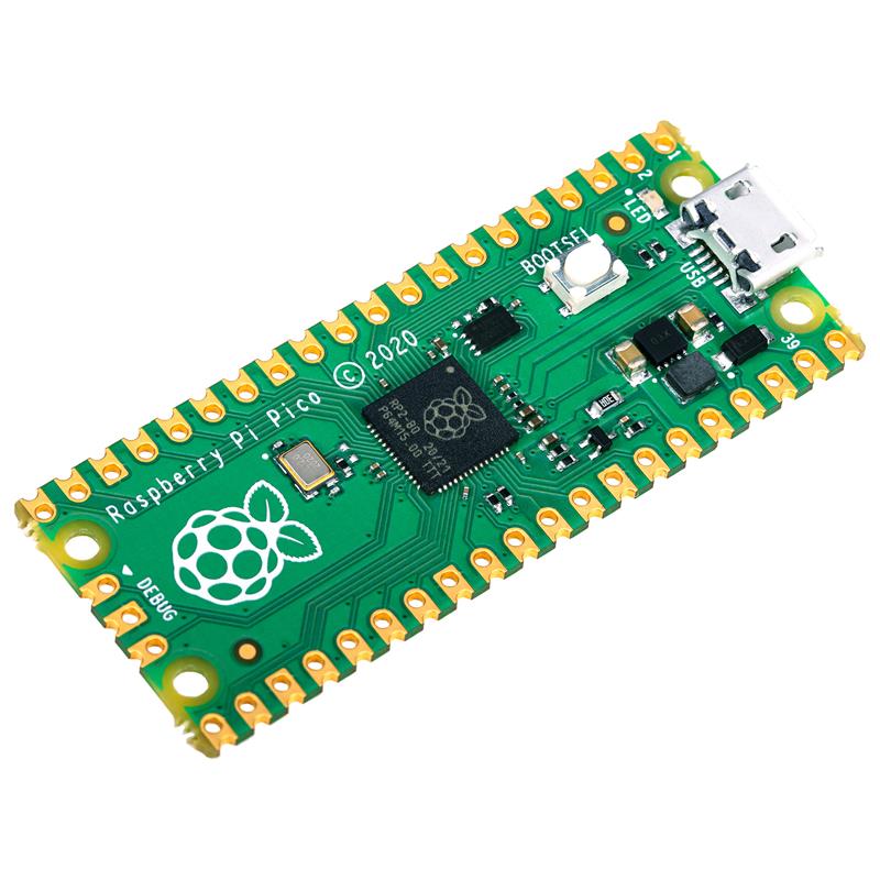
- Raspberry Pi Pico 2 board
- Adafruit PDM MEMS Microphone Breakout
- Half-size breadboard
- Jumper wires
- (optional) Slide switch
- (optional) Tactile button
The optional slide switch will be used as a toggle to disable or enable the noise suppression processing at run-time, while the optional tactile switch will provide a convenient way to reset the board.
Wire up the hardware as follows:
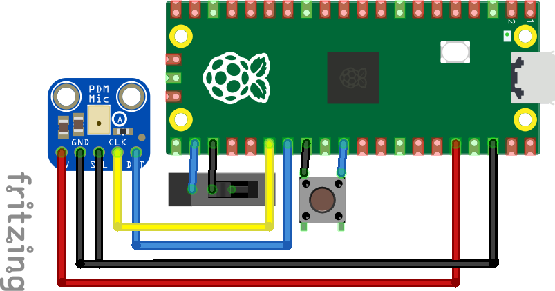 Wiring diagram of project
| Raspberry Pi Pico 2 | PDM MEMS Microphone Breakout | Slide switch (optional) | Tactile button (optional) |
|---|---|---|---|
| 3V3 (OUT) | 3V | ||
| GND | GNDSEL | Middle Pin | Bottom Pin |
| RUN | Top Pin | ||
| GPIO21 | DAT | ||
| GPIO22 | CLK | ||
| GPIO17 | Bottom Pin |
Once wired, your breadboard will look like this: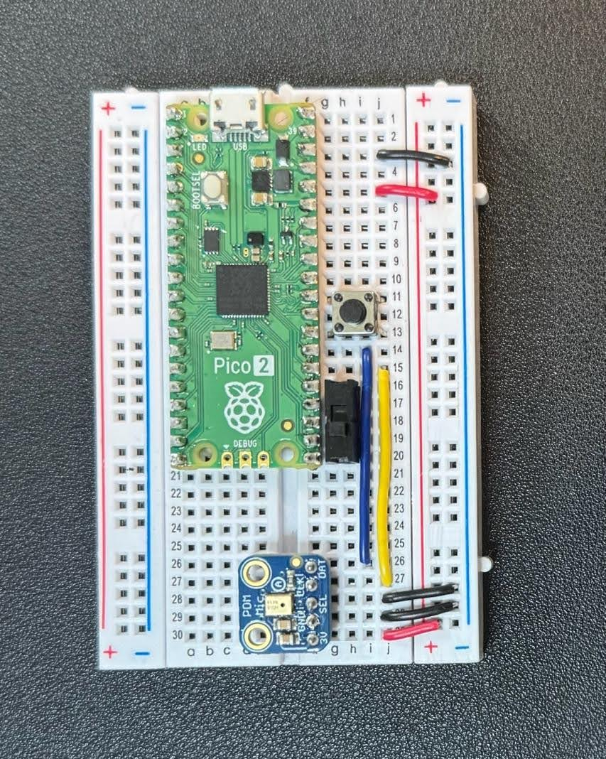
Software
The application will collect 480 16-bit samples from the PDM microphone at a sample rate of 16 kHz using the microphone-library-for-pico. This library combines the Programmable I/O (PIO) and Direct Memory Access (DMA) features of RP2350 with the OpenPDM2PCM library to convert the raw PDM data into Pulse-Code Modulation (PCM) format. The 16-bit PCM data is converted to a 32-bit floating point and denoised using the RNNoise algorithm. After this, the denoised frames are converted to 16-bit integers and sent over USB with the TinyUSB library. The USB transfer will send 16 denoised samples every 1 millisecond.
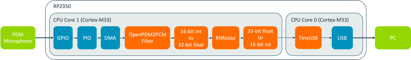
Block diagram of USB microphone with denoising
Both of RP2350’s Cortex-M33 cores are used in this application. Core 1 captures raw data from the PDM microphone, filtering and denoising it. Core 0 handles transferring the denoised data over USB using the TinyUSB library and RP2350’s USB interface.
The voice activity detection output of the RNNoise model will be displayed on the Pico 2’s built-in LED using Pulse Width Modulation (PWM). When VAD output is close to 1.0 the LED will be brighter, and when close to 0.0 the LED will be off.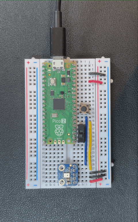
Recording of Pico 2 board using RNNoise VAD output to control brightness of the built-in LED with PWM
Source code for the application can be found in the examples/usb_pdm_microphone folder of the rnnoise-examples-for-pico-2 GitHub repo. The application can be compiled in a similar manner to the benchmarking application, using the following command:make
make rnnoise_usb_pdm_microphone
Once compiled, the file can be copied to the Pico 2’s USB disk after holding down the BOOTSEL button and resetting this board.examples/usb_pdm_microphone/rnnoise_usb_pdm_microphone.uf2
Testing
Once the application has been loaded to the board, you can test recording audio using Audacity by first clicking Audio Setup button -> Rescan Audio Devices, then Audio Setup button -> Recording Device -> MicNode, and clicking the record button.
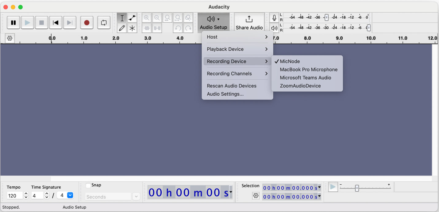
Selecting the MicNode as the Recording Device in Audacity
If you connected the optional slide switch, you could disable the noise suppression by sliding the switch towards the Pico 2’s USB connector, and re-enable noise suppression by sliding the switch away from the USB connector.
The recorded demo videos below use Pico 2 as a USB microphone, first with noise suppression off and then the same input with noise suppression enabled. See and hear the results of the noise suppression algorithm!
Audio recording of speech and wind noise with denoising disabled
Audio recording of speech and wind noise with denoising enabled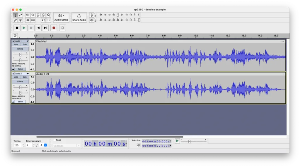 Screenshot of audio recording tracks. Top track: denoising disabled; bottom track: denoising enabled
Next steps
This blog demonstrated how the additional compute capabilities of Raspberry Pi Pico 2’s Arm Cortex-M33 CPU can be used to denoise real-time 16-bit audio data captured from a PDM microphone at 16 kHz with an ML model. The denoising algorithm leveraged the Cortex-M33’s floating point unit (FPU) and ran 16.87x faster than the Cortex-M0+ on the original Pico board. The application leveraged one CPU to capture, filter, and denoise data, and the other CPU to transfer the audio data to a PC over USB.
As a next step, you could modify the application to add Automatic Gain Control (AGC) before the denoised data is sent over USB to the PC. Alternatively, the denoised data can be used directly on the board, as input to another digital signaling processing (DSP) algorithm or a ML model that is run on Core 0 instead of the USB stack.
Original address: https://www.raspberrypi.com/news/real-time-ml-audio-noise-suppression-on-raspberry-pi-pico-2/


